

Top Chip Resistor Selections for High-Performance Circuit Designs
2026-07-08
In high-performance circuit design, every component choice matters—and chip resistors are no exception. From precision sensing to high-frequency signal paths, the right resistor can make or break your design’s stability and accuracy. At Milliohm, we understand these challenges intimately and have curated a selection of top-tier chip resistors that balance low resistance values, tight tolerances, and excellent reliability. Whether you’re pushing the limits of power management or refining a sensitive analog front-end, our picks are here to spark your next breakthrough. Dive in to see which resistors earned their place in our lineup—and why they might be the unsung heroes of your next project.
Thin Film vs. Thick Film: Which Resistor Technology Fits Your Design?
Resistor selection often comes down to a fundamental choice between thin film and thick film technologies. Thin film resistors are crafted by depositing a precise, uniform resistive layer onto a ceramic base, resulting in tight tolerances and low temperature coefficients. This makes them ideal for precision analog circuits, medical instruments, and aerospace applications where stability and accuracy are critical. On the other hand, thick film resistors use a paste-based resistive material that is screen-printed and fired, offering a wider range of resistance values and better power handling. Their sturdy construction and low cost suit them well for general-purpose electronics, power supplies, and automotive systems.
The physical construction differences lead to distinct performance characteristics. Thin film types exhibit lower noise and excellent high-frequency behavior due to their homogeneous structure, while thick film resistors can struggle with parasitic effects at higher frequencies. However, thick film components are more rugged and can withstand higher pulse loads, making them a reliable choice for surge-prone environments. It’s also worth noting that thin film resistors typically have lower voltage coefficients, ensuring consistent behavior across varying voltages—a feature crucial in measurement circuits.
Cost and availability often tip the scales. Thick film resistors dominate the market due to their straightforward manufacturing process and lower price point. If your design doesn’t demand extreme precision, they’re usually the practical option. Thin film resistors come at a premium but deliver the performance edge needed in high-end applications. Understanding these trade-offs helps you avoid over-engineering while maintaining the reliability and accuracy your project requires.
When Size Matters: Leveraging 0201 and Smaller Resistors
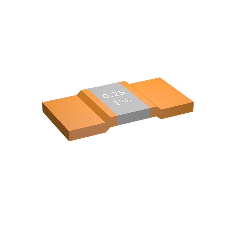
The electronics industry’s relentless push toward miniaturization has made 0201 and even smaller chip resistors not just an option but a necessity in modern circuit design. These diminutive components, measuring just 0.6 mm × 0.3 mm or less, free up valuable board real estate and enable tighter component packing, which is critical for wearables, medical implants, and high-density interconnect (HDI) boards. Yet, their reduced footprint brings challenges that go beyond simple soldering difficulties. Thermal management becomes precarious because the tiny surface area limits heat dissipation, demanding careful derating and layout considerations. Parasitic inductance and capacitance also shift, often for the better at high frequencies, but designers must revisit their impedance profiles to avoid unexpected signal integrity issues. Embracing these micro-scale parts requires a mindset that treats every millimeter as prime territory.
Handling and assembly processes for 0201 and smaller resistors demand precision that pushes the limits of standard pick-and-place equipment. Even minor pad design mismatches or solder paste inconsistencies can lead to tombstoning, where the component stands on end during reflow due to uneven thermal mass. To counter this, fabricators often turn to nitrogen atmospheres and finer solder powders, while designers play with pad geometries—extending termination lands or introducing slight asymmetries—to balance surface tension. On the inspection front, automated optical systems must be calibrated to detect micro-cracks or misalignments that are invisible to the naked eye. The payoff, however, is tangible: by adopting these resistors, RF circuits achieve lower insertion loss, and power distribution networks see a drop in inductance, making them indispensable for high-speed digital and wireless applications.
Beyond the technical execution hurdles, the supply chain and cost implications of using 0201 and smaller resistors are often underestimated. Their diminutive size means a single reel can hold tens of thousands of parts, reducing inventory bulk but increasing the risk of obsolescence if demand shifts. The tiny terminations also make rework a near-impossibility, so prototyping with these components often involves higher scrap rates and a shift toward simulation-driven design cycles. Interestingly, niche segments like automotive radar and advanced implantable devices have driven demand for 01005 (0.4 mm × 0.2 mm) resistors, where the space savings can be the difference between a functional prototype and a failed form factor. As the technology matures, the cost differential between standard 0402 and micro-resistors narrows, making size reduction a lever that teams pull not just for performance, but for competitive differentiation in an increasingly compact electronics landscape.
Taming Temperature Drift with Low TCR Resistors
Temperature drift can silently undermine the accuracy of precision circuits, especially in environments where thermal conditions fluctuate unpredictably. Even the most carefully designed analog front-end can see its performance erode when resistor values shift by just a few parts per million per degree. Low TCR (Temperature Coefficient of Resistance) resistors address this directly, using materials like metal foil or thin-film nichrome to keep resistance changes tightly constrained. Instead of battling drift with complex compensation algorithms, designers can simply specify a resistor that refuses to budge—turning a systemic vulnerability into a non-issue.
What sets low TCR resistors apart isn’t just their near-flat temperature response, but the quiet confidence they bring to a board. In a bridge sensor or a voltage reference, where every microvolt counts, swapping a standard thick-film part for a resistor with a TCR of ±2 ppm/°C transforms thermal hysteresis from a nagging error source into background noise you no longer need to worry about. It’s a hardware fix that feels almost lazy in its effectiveness—no exotic materials, no active cooling, just a component that holds its value while the ambient temperature swings from cold-soak to full-power operation.
Beyond the datasheet specs, the real payoff comes during testing and long-term deployment. Designs that rely on low TCR resistors tend to exhibit less calibration drift, fewer field returns, and a stability that makes precision feel effortless. The temperature chamber becomes a formality rather than a stress test, as the expected parametric shifts shrink to levels that barely register. For engineers who’ve chased thermal tails across a dozen prototypes, that kind of predictability isn’t just a performance metric—it’s peace of mind.
Power Resistors That Actually Handle the Heat
When it comes to managing high-power loads, standard resistors often crumble under thermal stress. The secret to true thermal resilience lies in the materials and construction. Wirewound resistors, for instance, use alloys like nichrome wound around ceramic or fiberglass cores, allowing them to dissipate heat efficiently without compromising their resistive properties. Their robust design means they don't just survive repeated power surges—they maintain stability, with some variants capable of operating at surface temperatures exceeding 300°C without derating. It's this inherent toughness that makes them the backbone of industrial braking systems and power supplies.
But handling heat isn't just about withstanding high temperatures; it's about getting rid of heat effectively. That's where thermal design makes all the difference. Modern power resistors often incorporate integrated heatsinks, finned aluminum housings, or even fillers that improve thermal conductivity. Some are purpose-built for liquid cooling, circulating coolant directly through the resistor body. This active thermal management ensures that even in compact electronic assemblies, the resistor can dump hundreds of watts of heat into the environment silently and reliably. Without such design features, localized overheating would cause failure in minutes.
Finally, application demands shape what "handling the heat" really means. In regenerative energy systems, resistors absorb massive pulses of energy and must radiate that heat away quickly between cycles. For locomotive dynamic braking, resistor grids are cooled by forced air, expelling enough heat to warm a small building. The key is matching the resistor's thermal capacity and dissipation rating to the specific load profile. It's not about overengineering it; it's about choosing the right technology—whether thick film, wirewound, or bulk ceramic—so that the resistor can take the heat day in and day out, without ever becoming the weak link.
High-Frequency Designs: The Hidden Impact of Chip Resistor Parasitics
When working with chip resistors in low-frequency circuits, their behavior is almost perfectly resistive. However, as frequencies climb into the hundreds of megahertz and beyond, the parasitic inductance and capacitance intrinsic to these components begin to distort their impedance characteristics. These parasitic elements stem from the resistor's internal construction—the resistive element, terminations, and even the cut of the laser trim can introduce unwanted reactance. Ignoring these hidden effects can easily derail a high-frequency design that was otherwise carefully planned.
The most troublesome consequence is the formation of a parasitic LC network that can resonate at certain frequencies, causing the effective impedance to spike or plummet away from the nominal resistance value. For example, a resistor that should act as a termination may instead reflect signals due to a sharp impedance change, or a biasing network might inject noise at an unexpected resonant peak. This behavior becomes particularly severe in designs where chip resistors are used in feedback paths, attenuators, or matching networks, where precise impedance control is critical.
To mitigate these issues, designers often turn to specialized high-frequency resistors built with reduced parasitics, such as thin-film types with minimal internal inductance. Even then, PCB layout plays a decisive role: keeping traces short, using proper grounding, and avoiding unnecessary vias can minimize the external parasitics that compound the component's internal ones. In practice, it is rarely about eliminating parasitics entirely, but about understanding their impact and designing around them to keep the circuit's performance within spec.
Beyond Datasheet Specs: Real-World Reliability Factors
Datasheet specs tell only part of the story. In the lab, components might meet every listed parameter, yet once they're deployed in the field, things can change dramatically. Temperature swings, vibration, humidity, and unpredictable power fluctuations expose weaknesses that no bench test can fully replicate. Engineers quickly learn that a component's true reliability is shaped by how it handles these real-world stresses over time, not just its initial tolerance ranges.
Another often overlooked factor is manufacturing variation. Even within a single production batch, subtle differences in material purity or assembly tightness can lead to divergent long-term behavior. That's why experienced designers look beyond the datasheet's typical curves and instead study field failure reports, warranty data, and teardowns of aged equipment. These sources reveal patterns like electromigration in connectors or dielectric breakdown that accelerated life testing might miss entirely.
Ultimately, robust design requires a mindset shift from “meets spec” to “withstands reality.” It means building in extra derating, choosing components with proven track records in similar harsh environments, and validating performance under real load profiles rather than ideal conditions. This approach turns reliability from a paper promise into a measurable, field-proven attribute.
FAQ
In precision analog circuits, a chip resistor needs tight tolerance (often 0.1% or better) and an exceptionally low temperature coefficient of resistance, ideally below 25 ppm/°C. Thin film types are typically the go-to because their construction yields superior stability and lower noise compared to thick film. Look for components with established long-term drift specs, as even tiny resistance shifts can degrade gain accuracy or offset voltages over time.
Start by calculating the worst-case power dissipation, then apply a hefty derating factor—typically 50% or more—to account for elevated temperatures and reduced airflow in compact layouts. High-density boards often run hot, so check the resistor's power derating curve and consider using a larger package size or a component with a wide terminal design that improves heat dissipation without sacrificing real estate.
Thin film resistors exhibit lower current noise and more predictable high-frequency behavior because of their uniform resistive layer and reduced stray capacitance. In audio or RF signal paths this translates to cleaner, more linear performance. Thick film parts, while cost-effective, can introduce excess noise and non-linearities that mask subtle details in sensitive stages.
Temperature coefficient tells you how much the resistance drifts as ambient or self-heating temperatures change. For precision applications like reference voltage dividers or sensor conditioning, even a drift of 50 ppm/°C can cause unacceptable errors across a wide operating range. Choosing a low TCR resistor—often thin film or metal foil—keeps the design stable without complex compensation schemes.
Tolerance defines the maximum initial deviation from the nominal value. In a simple two-resistor divider, the output voltage error is roughly the sum of the individual tolerances, so using 1% resistors can yield a worst-case error near 2% if they drift in opposite directions. Matching or using tight-tolerance parts (0.1%) dramatically improves accuracy, especially in circuits that rely on precise ratio tracking rather than absolute value.
Yes, look for components explicitly characterized for microwave or RF use. These often come in flip-chip or small outline packages with minimized parasitic inductance and capacitance. Thin film resistors on alumina substrates are common, and some manufacturers offer parts with wrap-around terminations optimized for low return loss up to several GHz. Always check the vendor’s S-parameter data to ensure impedance characteristics hold up at your target frequency.
Resistor noise comes from thermal agitation (Johnson noise) and, in some constructions, excess noise due to current flow. To reduce it, keep resistance values as low as practical for your noise budget, use metal film or thin film resistors which have inherently lower excess noise, and avoid carbon composition types entirely. Also, pay attention to PCB layout—minimizing loop area and keeping sensitive nodes away from digital traces helps prevent noise pickup.
Conclusion
Selecting the right chip resistor can make or break a high-performance design, but the sheer variety often obscures the trade-offs. Thin film resistors offer superior precision, low noise, and tight tolerances, making them ideal for signal conditioning and feedback loops, whereas thick film excels in cost-sensitive, general-purpose roles. As designs shrink, 0201 and even 01005 packages solve real-estate constraints, though they demand careful thermal management and assembly. Temperature drift is another silent performance killer—resistors with TCR below 25 ppm/°C are crucial in precision analog circuits to maintain accuracy across environments.
Power dissipation is rarely as straightforward as a datasheet rating; actual heat handling depends on PCB layout, copper area, and ambient conditions, especially in automotive or industrial settings. At high frequencies, parasitic inductance and capacitance turn a humble resistor into a filter or an oscillator, so non-standard terminations and flip-chip geometries are worth exploring. Yet real-world reliability often hinges on factors invisible in spec tables: pulse handling, sulfur-resistant terminations for harsh atmospheres, and mechanical robustness under vibration. By balancing these electrical and environmental dimensions, engineers can navigate beyond top-line specs and secure a resistor that truly fits the circuit’s long-term purpose.
Contact Us
Contact Person: Yuying Gao
Email: [email protected]
Tel/WhatsApp: +86 18926013721
Website: https://en.milliohm.net/