

HDMI Coaxial Cable Manufacturer Guide for Reliable AV Signal Transmission
2026-11-16
Nothing ruins a movie night faster than a flickering screen or sudden signal dropout. For installers and home theater enthusiasts alike, the choice of HDMI coaxial cable can make or break the entire AV experience. That's where a trusted manufacturer like EBCYX steps in — combining precision engineering with real-world reliability. In this guide, we'll break down what to look for in an HDMI coaxial cable manufacturer, so you can deliver flawless signal transmission every time.
Choosing Conductor Materials That Keep 4K Signals Intact Over Long Runs
The most overlooked issue in long 4K runs is skin effect. At the 6 Gbps data rates used by HDMI 2.0, signals travel mostly on the conductor surface, so surface condition and plating quality affect eye pattern more than bulk purity. Oxygen-free copper that is oxidized or rough can show noticeably higher high-frequency loss, while silver-plated copper's advantage is not the conductivity number itself but a uniform, dense silver layer that lowers surface resistance. Many installers get stuck on whether a cable is "pure copper" and miss the plating thickness, annealing, and stranding details that matter more.
Past 15 meters, simply increasing copper wire gauge rarely preserves a stable 4K signal. Copper-clad aluminum or copper-clad steel may look fine for DC, but at high frequency the skin depth is so shallow that the signal almost never reaches the inner steel or aluminum, while the outer copper layer is often too thin, causing attenuation and return loss to jump. If budget allows, hybrid fiber or pure fiber is clearly more reliable beyond 30 meters; if copper is a must, choose solid pure copper, AWG 24 or thicker, and foam insulation with a low dielectric constant instead of relying on marketing names for the conductor.
When selecting cable, don't be misled by words like "silver-plated" or "single-crystal copper." Pay more attention to attenuation per 100 feet, impedance consistency, and shielding coverage listed by the manufacturer. Shielding affects long 4K runs as much as the conductor itself: a foil-plus-braid double shield reduces external noise and crosstalk, but overly tight shielding adds capacitance and hurts the high-frequency signal. The practical approach is to measure or estimate the link budget for your actual cable length, then decide between a thicker copper cable or a switch to fiber, rather than expecting a miracle conductor to solve every problem.
Why Shielding Design Makes or Breaks Coaxial AV Performance
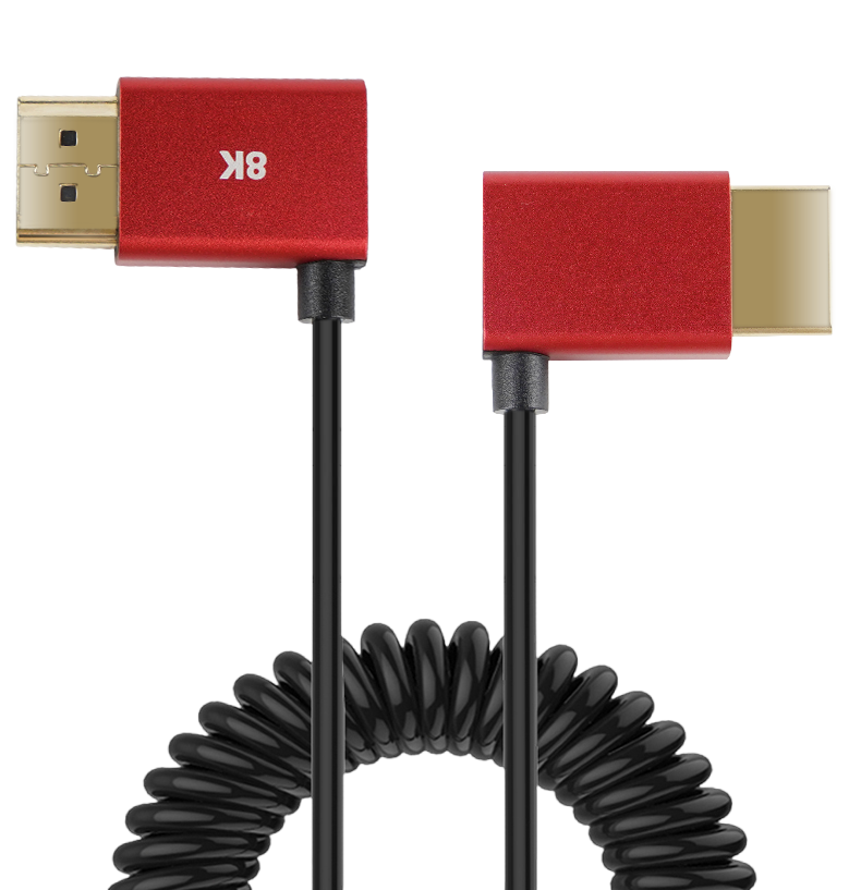
Shielding in coaxial AV cables often gets treated as an afterthought, yet it dictates whether you get a clean signal or a mess of interference. The basic idea is simple: an outer conductive layer blocks electromagnetic noise from reaching the center conductor. But real-world performance hinges on details most specs sheets gloss over—braid coverage percentage, foil type, and how the shield is terminated. A 40% braid might look fine on paper, but in a dense urban environment full of Wi-Fi, cellular, and broadcast signals, that sparse weave lets enough noise through to degrade picture quality or introduce audible hum. Professionals learn to test cables in the actual installation environment, not just on a bench.
Another overlooked factor is the relationship between shield design and flexibility. Dense braided shields offer superior rejection but make the cable stiff, which can lead to connector strain or even micro-fractures in the shield over repeated bending. Foil shields are cheap and effective at high frequencies, but they tear easily and rely on a drain wire that can become intermittent. The best designs often combine foil and braid, yet the manufacturing quality varies wildly—cheap cables may have foil that’s poorly bonded or a braid with inconsistent coverage. For fixed installations, rigidity is acceptable; for camera or stage work, a more flexible braid with slightly lower coverage might outperform a fragile foil-heavy alternative in the long run.
Termination is where shielding truly succeeds or fails. A perfect shield means nothing if the connector’s metal shell isn’t bonded to it around the full circumference. Many installers crimp or solder only the drain wire, leaving gaps that act like slot antennas at GHz frequencies. The result is intermittent dropouts that get blamed on the source or display. Proper cable assembly requires 360-degree contact, either through a crimping ferrule or a well-designed compression connector. After installation, a simple test with a portable spectrum analyzer or a known noisy environment can reveal whether your shielding design actually holds up—because in the real world, the shield is only as good as its weakest mechanical connection.
Connector Termination Practices That Prevent Signal Dropouts
A solid connector termination starts with the conductor, not the tool. Strip back just enough insulation to seat the wire fully inside the barrel—overstripping leaves exposed strands that invite shorts, while understripping prevents the crimp from biting into copper. When crimping, use a ratcheting tool matched to the connector’s exact die size; the ratchet should cycle fully before releasing. A half-engaged crimp is a common root cause of intermittent dropouts, especially in high-vibration environments.
For solder-type terminations, heat the joint until the solder flows into the cup from the opposite side of the iron, but don’t dwell long enough to wick solder up under the insulation. That stiffens the wire and creates a stress point that fractures over time. Finish by giving each terminated lead a firm but controlled tug—about the force of pulling a sticky drawer open. If the connection survives that, it’s far more likely to survive field use.
Don’t overlook strain relief. A properly crimped or soldered joint can still fail if the cable is free to flex right at the backshell. Use the connector’s built-in clamp or a short length of adhesive-lined heat shrink to bridge the transition from rigid termination to flexible cable. This spreads bending stress over a wider area and keeps the termination itself stationary, which is what actually prevents those maddening signal dropouts.
Balancing Flexibility and Durability in Cable Jacket Selection
Every engineer eventually hits the same wall: a cable jacket that bends beautifully but shreds after six months in the field, or one that survives a decade of abuse yet fights you on every single install. The sweet spot isn't found on a datasheet. It emerges from asking how the cable will actually live its life, not just what temperatures or chemicals it will meet on paper.
Start with movement. If the application involves continuous flexing, robotic arms, or tight routing inside a handheld device, the jacket must yield without micro-cracking. That usually means thermoplastic elastomers or specially formulated PVC blends with high elongation at break. But pure flexibility invites abrasion. A cable dragging across sharp edges, concrete, or repeated cable-on-cable contact will wear through a soft jacket long before the conductors fail. Here, a tougher polyurethane or a cross-linked compound may be worth the slight loss in pliability.
The practical trick is layering your thinking. Use a flexible inner jacket for strain relief and a harder outer skin for abrasion resistance, or choose a single material that sits in the middle: not too stiff to route, not too soft to survive. Then validate with your own abuse test, something closer to reality than a standardized scrape. Roll it under a chair, drag it across the floor you actually have, yank it through a conduit. Because when flexibility and durability finally balance, nobody notices the cable at all. They only notice the machine still running.
Factory Testing Protocols That Catch Intermittent AV Faults
Intermittent faults in autonomous vehicle systems are the worst kind of gremlin: they appear only under specific thermal loads, vibration profiles, or timing coincidences, then vanish the moment a technician opens the hood. Standard pass/fail diagnostics won't find them. What works is a layered testing protocol that treats the AV as a living system, not a static assembly. Start by forcing temperature cycles across the full operating range while monitoring the low-voltage CAN bus for dropped frames or retransmission spikes. A single missing message every few hundred cycles might seem harmless, but in a safety-critical stack it can cascade into sensor fusion drift.
Next, introduce controlled vibration and harness flexing during functional tests. Many intermittent AV faults trace back to micro-fretting in connectors or hairline cracks in PCB traces that only open under mechanical stress. Use a shaker table driven by road-load profiles recorded from actual test routes, and run it while the vehicle's compute units execute a full perception-planning-act loop. The key is to log not just errors, but also borderline events: a camera link that briefly drops to marginal signal integrity, a time-sync offset that creeps past tolerance for one second. Those near-misses are the early warnings of a hard failure waiting for the worst possible moment.
Finally, build a fault-injection harness that deliberately degrades signals, supplies, and ground paths, then confirm that your monitoring stack catches the degradation before any critical function is compromised. This isn't about proving the AV works when everything is perfect; it's about proving the vehicle can detect its own incipient failures. That self-awareness, validated on the factory floor, is what separates a system that merely passes a bench test from one that survives years of real-world chaos.
Installation Tips for Routing HDMI Coaxial Without Signal Loss
When routing HDMI over coaxial cable, the first thing that often trips people up is ignoring the bend radius. Coax is tougher than fiber, but kinking it behind a wall plate or forcing a tight corner inside a conduit will cause impedance bumps that eat away at high-frequency signals. Keep every turn at least five times the cable's outer diameter, and if you must make a 90-degree change, use a sweep elbow rather than a sharp right-angle connector.
Connector quality matters far more than most installers expect. Crimping on cheap BNC or F-type ends without the proper die set leaves micro-gaps between the shield and the body, which become entry points for noise and reflections. Spend the extra few minutes to strip the dielectric precisely, fold the braid completely over the ferrule, and verify continuity with a multimeter before sealing things up. A tiny bit of oxidation at this junction will degrade 4K signals long before you notice any visible damage.
Finally, keep your coax run away from AC power lines and fluorescent ballasts. Even well-shielded cable can pick up induced hum or switching noise if you zip-tie it parallel to a Romex bundle for ten feet. Cross power cables at 90 degrees when you have to intersect, and leave at least six inches of separation wherever possible. If the run passes near a dimmer switch or an HVAC blower, consider adding a ferrite choke at the display end—it's cheap insurance against random dropouts that only show up when the room gets warm.
FAQ
Look for documented impedance control, consistent dielectric foaming, and shielding that stays intact after repeated bending. The best shops publish return loss and skew measurements for their actual cable assemblies instead of just quoting raw cable specs.
A solid or silver-plated copper center conductor helps high-frequency edges survive long runs. Foamed polyethylene dielectric keeps capacitance low, while dual or triple shielding—often foil plus high-coverage braid—protects the TMDS channels from external noise that causes sparkles or dropouts.
Coaxial cable handles high-bandwidth HDMI signals with lower inherent skew than twisted pairs and is often easier to terminate in the field than fragile fiber. For moderate distances, a well-built coax balun or converter can deliver more predictable results without adding compression or EDID headaches.
You want to see eye pattern testing at the maximum rated data rate, time-domain reflectometry for impedance discontinuities, and swept return loss measurements up to at least 3 GHz. Some manufacturers also run bit error rate tests over a range of temperatures to catch marginal solder joints or connector seating issues.
Poor shielding allows electromagnetic interference to couple into the high-speed differential pairs, which shows up as random video artifacts or audio clicks. A good coax design uses overlapping foil and high-coverage braid to maintain low transfer impedance, especially in racks with power cables, wireless mics, and lighting dimmers nearby.
Yes, but not in the native HDMI electrical format. It requires active transmitter and receiver modules that convert the HDMI TMDS signals to a format suited for coaxial transmission. The cable itself just provides a controlled impedance path; the electronics handle protocol, EDID communication, and HDCP handshakes.
Be wary of vague specs like 'supports 4K' without data rate or distance details, missing return loss plots, and no mention of connector crimp or solder process control. Also, a manufacturer that cannot explain how they maintain 75 ohm impedance across the entire assembly is likely hiding weak points at the terminations.
Ask the manufacturer for a distance-versus-resolution matrix measured with their own transmitter and receiver, not just a theoretical cable loss chart. Better yet, request a sample set and test it with your actual sources, displays, and EDID configuration before committing to a large order.
Conclusion
A dependable HDMI coaxial cable starts with conductor materials that preserve signal integrity over distance. Solid copper conductors with tight dimensional tolerances keep attenuation low and impedance stable, which matters when 4K video travels through hundreds of feet of coax. Equally important is shielding design. A foil plus high-coverage braid—sometimes double or triple layers—blocks electromagnetic interference that can introduce sparkles, audio dropouts, or complete signal loss in AV installations. Connector termination is where many cables fail; precise strip lengths, consistent crimp pressure, and proper solder joints prevent micro-reflections and intermittent disconnects. The outer jacket must balance flexibility for tight routing bends with enough durability to survive pulls through conduits and repeated handling without cracking.
Factory testing protocols separate reliable cables from marginal ones. Beyond simple continuity checks, manufacturers should run swept frequency response tests, time-domain reflectometry to spot impedance bumps, and cyclic bend or temperature stress tests that reveal latent intermittent faults. On the installation side, routing matters as much as the cable itself. Maintain the manufacturer’s minimum bend radius, keep coaxial runs away from power cables and fluorescent ballasts, and use strain relief at both ends so connector joints are not loaded. Leave a small service loop for future re-terminations. When all these factors—conductor, shield, termination, jacket, testing, and careful installation—work together, HDMI coaxial links deliver stable, artifact-free AV signals over long runs without requiring active repeaters or costly fiber alternatives.
Contact Us
Contact Person: David Yang
Email: [email protected]
Tel/WhatsApp: 8615814734054
Website: https://www.ebcyx.com/